


|
Navigation: Toolboxes > Mechatronics Toolbox > Servo Motor Editor > Theory > Basic Principles > Permanent Magnet Motors |
  
|
When permanent magnets are used in a motor, a magnetic field will be present with a magnetic flux density B. Suppose an electric coil is placed in this magnetic field. When an electric current i is forced to flow through this coil, a force acting on the coil will occur.
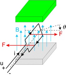
The resulting torque can be found as:
![]()
where Ktc(q) denotes the transfer of current to torque. It is a function of the angle, shape of the coil, magnetic field density, current distribution etc. When the current is kept equal to zero and we start to rotate the coil, a voltage will be induced. This voltage is called the electromotive force (EMF) and can be found as:
![]()
where Kec(q) denotes the transfer of speed to voltage. It is also function of the angle, shape of the coil, magnetic field density, current distribution etc. For an ideal coil the input power should be equal to the output power
![]()
and thus
![]()
In most literature the Kc(q) is calculated out of the magnetic field and coil distribution. Here it is simply assumed to be given and is called the torque function.
In normal operation a coil will have a resistance and inductance. A basic coil model is thus equal to:
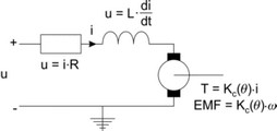
By a proper design of the motor, i.e. geometry of the coil windings, magnets etc., the torque function Kc(q) can be given a particular shape. Then by proper manipulation of the current a positive torque can be created during the whole rotation of the coil. All permanent magnet motors are based on this principle.