As described in the previous topic, the models in 2DSmallRotation library have two types of connection ports: 1D and 2D. The 1D port can represent movement in the x-direction, the y-direction or an angular displacement q.
![]()
The 2D port is a vector that contains all three degrees of freedom. The vector notation that is used in 20-sim is:
d.o.f. |
identity |
forces |
velocities |
x |
position |
P.F[1] [N] |
P.v[1] [m/s] |
y |
position |
P.F[2] [N] |
P.v[2] [m/s] |
q |
angle |
P.F[3] [Nm] |
P.v[3] [rad/s] |
The vector element number (1, 2 or 3) denotes the identity of the degree of freedom (x, y and q). To create meaningful models, we have to define the positive direction of each degree of freedom:
d.o.f. |
positive direction |
x |
from left to right |
y |
from bottom to top |
q |
counter clockwise |
This definition is arbitrary. We could as well define it any other way. In the 2DSmallRotation library we have chosen the definition above. It will help us define new models and interpret simulation results.
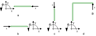
The connections between models only indicate how variables (forces and velocities) are transferred from one model to the other and vice versa. The orientation of the models in the Graph Editor (how they are drawn) is therefore not important. Flipping, rotating or moving a model does not change the model! All four representations in the figure below are the same although their individual models are oriented differently.

The figure above shows a point model in x-direction connected to a 2D body. The point indicates a force in x-direction that is applied to the body. Since we defined that the positive x-direction is from the left to the right, intuitively figure b leads to the correct interpretation.
This indicates a problem. Although all models describe the same behavior, we would intuitively interpret them differently. It is therefore useful to impose some rules to prevent misinterpretation of a model by other users.
| 1. | Preferably leave the orientation of the models of the 2DSmallRotation library as they pop up on the screen. |
| 2. | If necessary, only flip or rotate models in a direction that does not lead to misinterpretations. |
| 3. | If possible, draw 1D connections in the following direction: |
d.o.f. |
positive direction |
x |
from left to right |
y |
from bottom to top |
q |
from left bottom to right top |
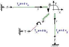
An example is shown in the figure below:


