


|
Navigation: Modeling Tutorial > Iconic Diagrams > Iconic Diagrams |
  
|
If we can represent the various parts of an ideal physical model by predefined models or components modeling is easy. In 20-sim a large library of components is available allowing you to create a model just by selecting the proper components and connect them according to the ideal physical model. To make modeling even more easy, the components are displayed in the editor by icons which look like the corresponding parts of the ideal physical model. In 20-sim these kind of models are called iconic diagrams (sometimes other simulation tools refer to this kind of modeling as component based modeling). 20-sim can automatically compute simulation code out of an iconic diagram and start a simulation.
Look again at the car suspension example. In the picture below at the right an iconic diagram is shown that has been entered in 20-sim. As you can see, the iconic diagram similar to the ideal physical model. Each component of the iconic diagram represents a physical process. For example the mass component represents the law of motion (F = m*a) and the spring represents the linear spring equation (F = k*x). The connections between the components in the iconic diagram represent ideal energy transfer between those components, i.e. no energy is stored, generated or dissipated.
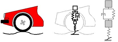
A iconic diagram model of a car suspension.
An iconic diagram describes a physical system as a number of physical concepts (the components) connected by energy flows (the connections).