


|
Navigation: Library > Signal > Sources > signalgenerator-sweep |
  
|
Signal\Sources
Default
Logarithmic
ZeroMean
Domains: Discrete, Continuous. Size: 1-D. Allowed in: Block Diagrams.
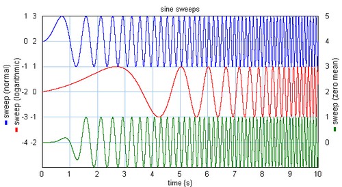
The output of this model is a linear sine sweep. The signal starts with angular frequency "omega_start" and ends at an angular frequency "omega_stop".
In the picture below the three available sweep functions are shown. The curve on top shows the linear sine sweep. The middle curve shows the logarithmic sine sweep and the bottom curve shows the linear sine sweep with zero mean.
Outputs |
Description |
output |
|
Parameters |
|
start_time stop_time amplitude omega_start omega_stop |
The start time of the sweep. The stop time of the sweep. The amplitude of the sweep. The start frequency of the sweep. The stop frequency of the sweep. |
The output of this model is a logarithmic sine sweep. Compared to the linear sine sweep the lower frequencies are stretched out and the higher frequencies are squeezed. The signal starts with angular frequency "omega_start" and ends at an angular frequency "omega_stop".
In the picture below the three available sweep functions are shown. The curve on top shows the linear sine sweep. The middle curve shows the logarithmic sine sweep and the bottom curve shows the linear sine sweep with zero mean. The middle curve clearly uses more time for the lower frequencies and less time for the higher frequencies.
Outputs |
Description |
output |
|
Parameters |
|
start_time stop_time amplitude omega_start omega_stop |
The start time of the sweep. The stop time of the sweep. The amplitude of the sweep. The start frequency of the sweep. The stop frequency of the sweep. |
The output of this model is a linear sine sweep with compensation in the first period to get a zero mean output. A zero mean is important when the signal is integrated twice. To prevent drift the mean should be zero. Double integrals can occur in physical systems. For example when a force sweep is applied to a mechanical system and the position is measured, the mean force should be precisely zero to prevent the system from drifting away. The signal starts with angular frequency "omega_start" and ends at an angular frequency "omega_stop".
In the picture below the three available sweep functions are shown. The curve on top shows the linear sine sweep. The middle curve shows the logarithmic sine sweep and the bottom curve shows the linear sine sweep with zero mean. The bottom curve differs slightly from the top curve in the first period.
Outputs |
Description |
output |
|
Parameters |
|
start_time stop_time amplitude omega_start omega_stop |
The start time of the sweep. The stop time of the sweep. The amplitude of the sweep. The start frequency of the sweep. The stop frequency of the sweep. |