Iconic Diagrams\Hydraulics\Valves\Basic Valves
Domains: Continuous. Size: 1-D. Kind: Iconic Diagrams (Hydraulics).
A shuttle valve is a type of valve which allows fluid to flow through it from one of two sources. Shuttle valves accept flow from two different sources (pa) and (pb) and divert the highest pressure to a single outlet port (p_out). Shuttle valves are commonly used in Load Sensing circuits and at a cylinder to measure the working pressure, as well as Brake circuits. Normal shuttle valve are mostly ball and poppet types valves.

The default implementation of the shuttle valve assumes ideal behaviour:
p.out.p = maximum(pa.p, pb.p)
pa.phi = pb.phi = 0;
This model sets the flows of the input ports to zero and assumes the output flow is zero as well. However the output flow is determined by the component that is connected with the output port. A warning is given when the output flow exceeds 1.0e-5 m3. If flows are important in your model, use the Spool Dynamics implementation of this model (see below).
Ports |
Description |
pa, pb p_out |
Input terminals of the valve. Output terminal. |
Causality |
|
fixed volume flow out pa fixed volume flow out pb fixed pressure out p_out |
|
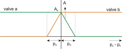
This implementation is equal to the default implementation but with modeled dynamics. A small pressure difference between the inlet ports pa and pb is enough to make the ball switch from one side to the other. This pressure is called the overlap pressure po.

Ports |
Description |
pa, pb p_out |
Input terminals of the valve. Output terminal. |
Causality |
|
fixed volume flow out pa fixed volume flow out pb fixed volume flow out p_out |
|
Parameters |
|
Q_max |
flow at maximum pressure drop [m3/s], Q_max > 0. |
p_max |
Maximum pressure drop over the valve [Pa], p_max > 0. |
f p_o |
Bandwidth of the valve dynamics [Hz], f > 0. Overlap pressure [Pa], p_o >= 0. |


