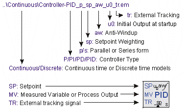
Two types of PID-controllers are available in this library. The first type of controllers use an error input and the second type of controllers use separate Setpoint (SP) and Measured Variable (MV) input.
Error Input
PID-Controllers with the error as a direct input signal, are all in series form. The name simply denotes the type of controller: P, PI, PD or PID. Two versions of each controller exists: continuous time and discrete time. They can be found in the subdirectories Continuous and Discrete.
Ports
All controllers have one input ports and one output port:
| 1. | error: The error between setpoint and measured variable. |
| 2. | output: The controller output. |
Parameters
Depending on the type of controller, the following parameters can be used:
| 1. | kd: The proportional gain of the controller. |
| 2. | tauD: The derivative time constant. |
| 4. | tauI: The integral time constant. |
Controller Wizard
A special form of controllers with error input is generated by the ControllerWizard.emx submodel. When you select this model and click Go Down the Filter Editor is opened, allowing you to specify controllers with frequency oriented parameters.
Separate Input
Controllers with separate inputs come in many forms. The naming denotes the type of controller and the options that are available. The type and options are also available in the model icons.

| 1. | Two versions of each controller exists: continuous time and discrete time. They can be found in the subdirectories Continuous and Discrete. Continuous-time controllers have icons with blue text and discrete-time controllers have icons with green text. |
| 2. | The first characters denote the type of controller: P, PD, PI or PID. |
| 5. | If an anti-windup scheme is incorporated, the term aw is added. |
Ports
All controllers have two inputs ports and one output port:
| 2. | MV: The measured variable (also called process variable). |
| 3. | output: The controller output. |
Parameters
Depending on the type of controllers, the following parameters can be used:
| 1. | K: The proportional gain of the controller. |
| 2. | Td: The derivative time constant. |
| 4. | Ti: The integral time constant. |
| 7. | Ta: The tracking time constant of the anti-windup scheme. |
Initial Values
Although most controllers have one or more internal states, the initial values of these states do not need to be set manually. You use the default values (0) at the start of a simulation. To get a desired output of the controller at startup , the parameter output_initial should be used.
Discrete Controllers
The discrete controllers that are available in the library are directly derived from their continuous counterparts, using approximation by backward differences. These discrete models have identical behavior, as long as the sample time is not chosen too low. Discrete loops in 20-sim are automatically detected and assigned a default sampletime. You can change the sample time in the Run Properties Editor (in the Simulator from the Properties menu select the Simulation command).
Variables
Some PID controllers (parallel form with anti-windup) have two internal variables that are of interest. PB_high and PB_low. These parameters are the upper and lower bound of the proportional band.
