


|
Navigation: Library > Iconic Diagrams > Hydraulics > Valves > Basic Valves > flowcontrolvalve |
  
|
Iconic Diagrams\Hydraulics\Valves\Basic Valves
Domains: Continuous. Size: 1-D. Kind: Iconic Diagrams (Hydraulics).
Flow control valves have the purpose to provide a constant flow, independent of the downstream pressure. The flow is obtained by means of a pressure difference controller using the pressure drop over an orifice. Therefore flow control valves always need a certain pressure drop before the desired flow can be achieved.
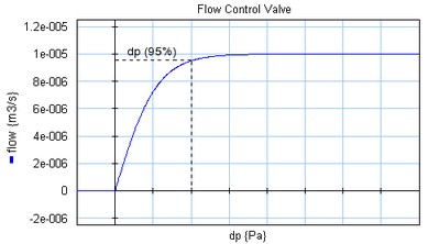
In this model the flow is modeled by an tanh function. The pressure drop is defined as the pressure where 95% of the desired flow rate is achieved.
dp = pa.p - pb.p
phi = if dp > 0 then
Q_set*tanh( (arctan(0.95)/p_drop) * dp) + GLeak * dp;
else
GLeak * dp
end;
Here phi is the desired flow and p_drop is the 95% pressure drop. Gleak is the conductance of laminar leakage flow when the valve is closed. The pressure at both ports has a lower limit that is equal to the vapour pressure. Therefore the actual equations used in this model are:
p1_lim = if pa.p < p_vapour then p_vapour else pa.p end;
p2_lim = if pb.p < p_vapour then p_vapour else pb.p end;
dp = p1_lim - p2_lim;
Ports |
Description |
pa, pb |
Both terminals of the hydraulic component. |
Causality |
|
fixed volume flow out pa fixed volume flow out pb |
|
Parameters |
|
Q_set p_drop GLeak
|
Desired flow [m3/s] pressure drop at 95% flow [Pa] Conductance of the laminar leakage flow [m3/s.Pa], GLeak >= 0! |