


|
Navigation: Modeling Tutorial > Iconic Diagrams > Orientation (Through) |
  
|
When simulating, you have to know how across and through variables are oriented to make a correct interpretation of what is happening. 20-sim can show the orientation when you select the Orientation Info option of the View menu.
Through variables in connections are always defined with respect to the components they are connected with. 20-sim automatically assigns an orientation for these through variables. This orientation can be made visible by selecting the Orientation Info command of the View Menu.
Through variables that are not of the mechanical domain are always shown with an arrow in the connection. The arrow indicates the direction of the positive flow. The figure below shows a negative current: i = -2e-5 A. This means the current flows in the opposite direction of the arrow.
Through variables of the mechanical domain are always shown with two arrows. The arrows indicate the direction of the positive force. The figure below shows a positive force: F = 0.45 N. This means the spring pushes with a force of F = 0.45 [N] upon the mass and the mass pushes with a force of F = 0.45 N upon the spring (note: a negative force would mean pulling instead of pushing).
This interpretation of forces in 20-sim is only valid when a positive velocity defined from the left to the right, and from the bottom to the top!
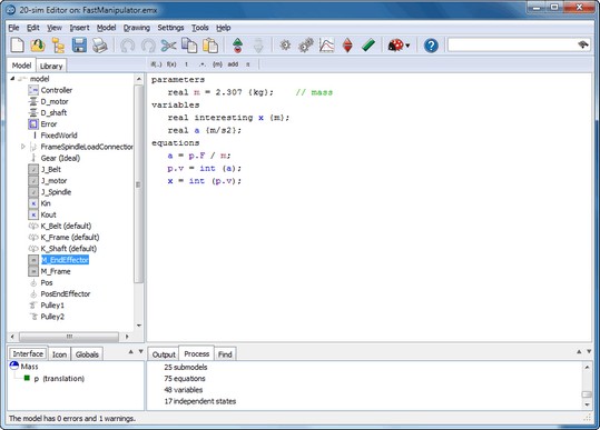
In submodels, you have to use the Type Editor to find out how through variables are defined. For example an ideal mass (see next figure) uses the option any number of terminals for its port (inspect the port in the Type Editor). The port equations are:
p.F = p1.F + p2.F
p.v = p1.v = p2.v;
The internal equations are:
p.v = (1/m)*int(p.F);
x = int(p.v);
where p1 and p2 are the ports to the connections at both sides of the mass. p1.v and p2.v are velocities defined with respect to the global reference. However, p.F (see also in the figure below) is the sum of the forces applied on both sides.
The definition of through variables depends on the definition of number of terminals of a port, which is shown in the Type Editor. To inspect the ports, put the mouse pointer on top of the Interface tab and select Edit from the right mouse menu.
| • | The geometrical layout of the iconic diagram does not have a meaning. If a resistor is drawn upside down, its current is still defined with respect to the resistor (flowing towards or from). If a mass is drawn upside down, its force is still defined with respect to that mass (pulling or pushing). |
| • | To show or hide the orientation of an Iconic Diagram select or deselect the Orientation Info option of the View menu. |