


|
Navigation: Library > Signal > Control > PID Control > Continuous > controller use |
  
|
All controllers must can be used as shown in the figure below. The upper part shows a continuous time controller and the bottom part shows a discrete time controller.
| 1. | An error signal is generated with a plus minus element. Its serves as an input of the controller. |
| 2. | The controller output is connected with the process input. |
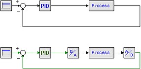
As shown in the figure, analog to digital convertors and digital to analog convertors should be used, when connecting a discrete-time controller to a continuous-time process.
| 1. | A setpoint signal is connected with the SP port of the controller. |
| 2. | The process output is connected with the PV port of the controller. |
| 3. | The controller output is connected with the process input. |
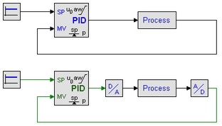
As shown in the figure, analog to digital convertors and digital to analog convertors should be used, when connecting a discrete-time controller to a continuous-time process.