


|
Navigation: Library > Signal > Logical > Boolean > Clock |
  
|
Signal\Logical\Boolean
Domains: Discrete, Continuous. Size: 1-D. Kind: Block Diagrams.
This model has a continuous-time and a discrete-time implementation.
| • | Continuous |
| • | Discrete |
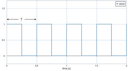
This models generates a logical continuous clock signal, i.e. a signal that changes from true (1) to false (0) and back, each period T with T = (1/frequency)
If the discrete implementation is chosen, the frequency must be smaller than half of the the sample frequency, otherwise not a good clock signal will result. To have the top part of the clock signal equally long to the down part, choose the frequency equal to the sample frequency divided by 2^n, with n an integer equal or larger than one.
Port name |
Data type |
Description |
Unit |
Range |
Parameters |
|
|
||
initial |
boolean |
initial output |
|
false/true |
frequency |
real |
clock frequency |
Hz |
> 0.0 Hz |
Outputs |
|
|
||
output |
boolean |
Clock output |
|
false/true |
Make sure that the simulation uses step sizes which are small enough to calculate the clock signal going up and going down: step size << clock period.