Using FFT-Analysis, the Fast Fourier Transform is used to calculate the frequency contents of simulation signal. Three representations are supported:
| • | Amplitude and Phase: This representation shows the amplitude and phase of the signal as function of the frequency, similar to a bode plot. If you want show the transfer function of a system, you have to choose the option Pair-wise transfer function, which is explained below in the FFT Settings. |
| • | Frequency Plot: This representation shows the frequency contents of the signal. Summation of the peak values yields the average power of the original time signal. |
| • | Power Spectral Density: This representation shows the frequency contents of the signal. Integration over the frequency range yields the average power of the original time signal. |

FFT plot showing the power spectral density.
FFT analysis can be performed in the Simulator by choosing the FFT Analysis command from the Tools menu. You can also choose to add an FFT plot in the Simulator tree. In both cases a new FFT plot is shown.
Plot Properties
You can define the FFT plot by opening the plot properties (from the menu choose Properties - Plot). Four tabs are shown: Plot Properties, X-Axis, Y-Axis and FFT Settings.
| • | The Plot Properties tab shows the general settings of the plot, similar to every standard plot. |
| • | The X-axis tab shows the X-Axis variable of the FFT input. The default value is time and should not be changed. |
| • | The Y-axis tab shows the variables that are selected to be shown as FFT curves, similar to every standard plot. |
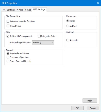
| • | The FFT-Settings tab shows the options that you can choose for the FFT plot. |
FFT Settings

Items
| • | Pair-wise transfer function: Shows an FFT with the frequency contents of the first plot variable subtracted from the second plot variable. Select this option if you want to show the FFT of a transfer function. The first plot variable is the input of the transfer function and the second plot variable is the output of the transfer function. |
| • | Show Peaks: Choose this option to show the peak values in the FFT plot. |
| • | Subtract DC-component: If your signal contains a DC-component, the resulting Spectral Density plot will show a high peak at 0 Hz, which may obscure all other frequencies. Choose Subtract DC-component, to remove this peak from the Spectral Density plot. |
| • | Integrate Data: You can integrate the FFT data to inspect the energy contents of each frequency. This option is useful for analyzing resonance frequencies. Integrated FFT-data will usually show a sudden increase exactly at these frequencies. |
| • | Frequency: Show the results in Herz or radians per second. |
| • | Output: select the desired representation of the frequency data: |
| • | Status Window: The bottom part of the window shows the number of simulation points and the chosen frequency range. |
Quality
The quality of an FFT plot depends on the contents of the time domain simulation:
| • | The number of simulation points per second, determine the frequency range of the FFT. If you want to increase the frequency range to higher frequencies, choose a smaller step size or a smaller maximum step size of the integration method. |
| • | The quality of the FFT depends on the total time of the simulation. Increase the finish time of the simulation to get a better FFT plot. |
| • | Make sure that you system is excited properly. If you give an input signal that does not contain higher frequencies, the FFT plot will not show them. |

