Iconic Diagrams\Mechanical\Rotation\Gears
Iconic Diagrams\Mechanical\Translation\Transmission
Domains: Continuous. Size: 1-D. Kind: Iconic Diagrams (Translation).
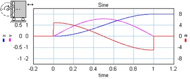
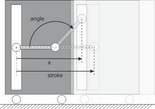
This models represents a cam and rod mechanism. If the input shaft is rotating with a constant speed, the output motion is a pure sinusoidal.

The mechanism starts with the carriage in the most left position. The arm length is half of the stroke:

The mechanism is ideal, i.e., it does not have inertia, friction or geometrical limitations. It has one rotation port (p_in) and one translation port (p_out). The causality of this model is always mixed: one port has a force out causality while the other has a velocity out causality:
p_in.T = i * p_out.F
p_out.v = i * p_in.omega
The transmission ratio (i) is the ratio of the velocities of both ports (in fact a sinusoidal function of the shaft angle).
Ports |
Description |
p_in p_out |
Driving axis (Rotation) Output port with resulting motion (Translation) |
Causality |
|
fixed torque out p_in fixed velocity out p_out |
|
Parameters |
|
stroke |
Stroke of the translation port (is equal to half the length of the rod). |


