


DoubleSwitch |
  
|
Iconic Diagrams\Electric\Components
Level
Amplitude
Domains: Continuous. Size: 1-D. Kind: Iconic Diagrams (Electric).
This model represents an almost ideal switch. The switch connects port p1 with p2 when the input signal is larger than the threshold value vt and connects port p1 with p3 when the input signal is smaller or equal to the threshold value vt.
The heart of the model consist of two resistances that can be changed by an input signal from almost zero (on) to a very large value (off). By proper selection of the on and off resistances, they can be effectively zero and infinity in comparison to other circuit elements.
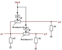
Layout of the switch model.
The equations of the resistances are:
R = if input > vt then Ron else Roff end;
p.u = R * p.i;
Ports |
Description |
p1, p2, p3 input |
The electric ports (Electric). The switching signal. |
Causality |
|
indifferent p1, p2, p3 |
|
Parameters |
|
R1\R R2\R R3\R |
Ground resistance at port 1 [Ohm] Ground resistance at port 2 [Ohm] Ground resistance at port 3 [Ohm] |
Resistance12\Ron Resistance12\Roff Resistance12\vt |
Resistance between p1 and p2 when switch is turned on [Ohm] Resistance between p1 and p2 when switch is turned off [Ohm] Threshold value between p1 and p2, switch is turned on when input > Resistance12\vt |
Resistance13\Ron Resistance13\Roff Resistance13\vt |
Resistance between p1 and p3 when switch is turned on [Ohm] Resistance between p1 and p3 when switch is turned off [Ohm] Threshold value between p1 and p3, switch is turned on when input > Resistance13\vt |
This model represents an almost ideal switch. The switch connects port p1 with p2 when the absolute value of the input signal is larger than the threshold value Resistance12\vt and connects port p1 with p3 when the absolute value of the input signal is smaller or equal to the threshold value Resistance13\vt.
The heart of the model consist of two resistances that can be changed by an input signal from almost zero (on) to a very large value (off). By proper selection of the on and off resistances, they can be effectively zero and infinity in comparison to other circuit elements.
Layout of the switch model.
The equations of the resistances are:
R = if abs(input) > vt then Ron else Roff end;
p.u = R * p.i;
Ports |
Description |
p1, p2, p3 input |
The electric ports (Electric). The switching signal. |
Causality |
|
indifferent p1, p2, p3 |
|
Parameters |
|
R1\R R2\R R3\R |
Ground resistance at port 1 [Ohm] Ground resistance at port 2 [Ohm] Ground resistance at port 3 [Ohm] |
Resistance12\Ron Resistance12\Roff Resistance12\vt |
Resistance between p1 and p2 when switch is turned on [Ohm] Resistance between p1 and p2 when switch is turned off [Ohm] Threshold value between p1 and p2, switch is turned on when abs(input) > Resistance12\vt |
Resistance13\Ron Resistance13\Roff Resistance13\vt |
Resistance between p1 and p3 when switch is turned on [Ohm] Resistance between p1 and p3 when switch is turned off [Ohm] Threshold value between p1 and p3, switch is turned on when abs(input) > Resistance13\vt |
To get a simple switching behavior, pay attention to chose the parameters Resistance12\vt and Resistance13\vt equal. When these parameters are not chosen equal a more complex switching behavior can be obtained.