


|
Navigation: Library > Iconic Diagrams > Hydraulics > Restrictions > orifice |
  
|
Iconic Diagrams\Hydraulics\Restrictions
Domains: Continuous. Size: 1-D. Kind: Iconic Diagrams (Hydraulics).
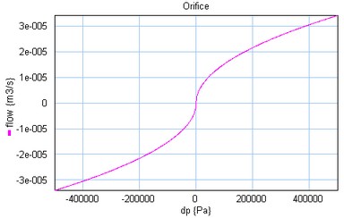
This model describes the laminar/turbulent flow through an orifice if no cavitation occurs. The flow depends on the pressure difference:
dp = pa.p - pb.p
phi = sign(dp) * Cd * A * sqrt( (2/rho) * abs(dp) ) + GLeak * dp;
Here Cd the discharge coefficient, A the orifice area, rho the fluid density, GLeak the conductance of laminar flow and dp the pressure difference. The discharge coefficient depends on the shape of the orifice and is generally not listed in data sheets. Therefore we will write the turbulent flow with nominal parameters. Given a nominal pressure drop p_nom we find a nominal flow:
Q_nom = Cd * A * sqrt( (2/ rho) * p_nom)
we can use this to rewrite the flow equation as:
phi = Q_nom * sqrt( dp / p_nom)
Similar we can write the laminar leakage flow as
Q_leak = G * p_nom
we can use this to rewrite the complete orifice equation as:
phi = Q_nom * sqrt( dp / p_nom) + (Q_leak/p_nom)*dp
The pressure at both ports has a lower limit that is equal to the vapour pressure. Therefore the actual equations used in this component are:
p1_lim = if pa.p < p_vapour then p_vapour else pa.p end;
p2_lim = if pb.p < p_vapour then p_vapour else pb.p end;
dp = p1_lim - p2_lim;
Ports |
Description |
pa, pb |
Both terminals of the hydraulic component. |
Causality |
|
fixed volume flow out pa fixed volume flow out pb |
|
Parameters |
|
Q_nom Q_leak p_nom |
Turbulent flow at nominal pressure drop [m3/s] Leakage flow at nominal pressure drop, make 1e-8 if unknown [m3/s] Nominal pressure [Pa]. |