


|
Navigation: Library > Iconic Diagrams > Hydraulics > Valves > Basic Valves > PressureCompensator |
  
|
Iconic Diagrams\Hydraulics\Valves\Basic Valves
Domains: Continuous. Size: 1-D. Kind: Iconic Diagrams (Hydraulics).
The flow through the element is laminar or turbulent depending on the pressure drop p_ab over pa and pb:
p_ab = pa.p - pb.p;
phi = sign(p_ab) * Cd * A * sqrt( (2/rho) * abs(dp) ) + GLeak * p_ab;
The opening A depends on the pressure drop p_xy over pa and pb:
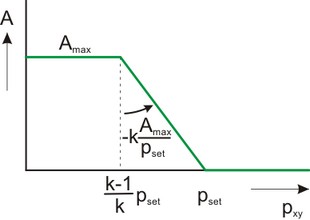
The maximum opening A_max is determined by the maximum flow phi_max at the maximum pressure drop p_in_max over the component:
A_max = phi_max / ( Cd * sqrt( (2/rho) * p_in_max ) );
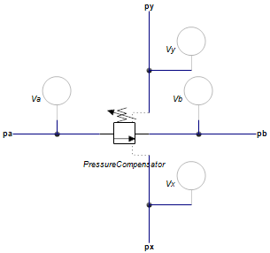
The opening is at its maximum value when the differential pressure across it sensing ports px and py is below the pressure ((k-1)/k)*p_set. If the differential pressure across it sensing ports px and py is too high, the opening is closed. In between it varies between fully open and fully closed. The speed of response of the components is determined by the proportional gain k (typical choose k = 2 to 5). The proportional gain determines the slope of the valve opening. If k is large the regulator will respond quickly but also induce oscillations in the circuit.
The valve is implemented with second order spool dynamics. I.e. the spool opening is characterized by the bandwidth (f) and damping (d).
Ports |
Description |
pa, pb px, py |
Input and output terminals of the component. Sensing terminals of the component. These are used to measure the pressure and have almost zero flow. |
Causality |
|
fixed volume flow out pa fixed volume flow out pb fixed volume flow out px fixed volume flow out py |
|
Parameters |
|
GLeak p_set p_in_max phi_max
f k
|
Conductance of the laminar leakage flows [m3/s.Pa], GLeak >= 0. Desired differential pressure over xy (px.p - py.p), [Pa] maximum inlet pressure, [Pa] maximum flow at maximum inlet pressure (pa.p) and zero outlet pressure (pb.p), [m3/s] natural frequency of the second order spool dynamics [Hz] proportional gain [-] |