Iconic Diagrams\Electric\Components
Default
Universal
Domains: Continuous. Size: 1-D. Kind: Iconic Diagrams (Electric).
This model represents an ideal operational amplifier. The input resistance is infinite and the output resistance is zero. The port p_in of the OpAmp model has separate high and low terminals:
p_in.u = p_in_high.u - p_in_low.u;
p_in_high.i = p_in_low.i = p_in.i = 0;
p_out.u = A*p_in.u;
Ports |
Description |
p_in_high, P_in_low p_out |
Both terminals of the input port p_in (Electric). Output port (Electric). |
Causality |
|
fixed current out p_in fixed voltage out p_out |
|
Parameters |
|
A |
Amplification [] |
This model represents an operational amplifier with a first order decreasing voltage amplification.

The amplification is parameterized by a DC-gain (A) and a cut-off frequency (f). This yields a unity gain frequency of:
unity gain frequency = A*f;
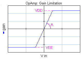
The gain is limited to yield an output that is between the positive (VDD) and negative (VEE) supply voltage.

The input resistance is infinite and the output resistance is equal to the parameter R. The port p_in of the OpAmp model has separate high and low terminals:
p_in.u = p_in_high.u - p_in_low.u
p_in_high.i = p_in_low.i = p_in.i = 0;
p_out.u = Adiff*p_in.u - R*p_out.u;
where Adiff is a dynamic gain according to the bode and gain plot.
Ports |
Description |
p_in_high, P_in_low p_out |
Both terminals of the input port p_in (Electric). Output port (Electric). |
Causality |
|
fixed current out p_in preferred voltage out p_out |
|
Parameters |
|
A f VDD VEE R |
DC gain or DC Amplification Cut-off frequency [Hz] Positive supply voltage [V], choose VDD > VEE! Negative supply voltage [V], choose VDD > VEE! Output impedance [Ohm] |


