


|
Navigation: Modeling Tutorial > Iconic Diagrams > Ports |
  
|
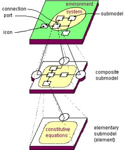
A port is a location where a component can exchange information (in case of a signal port) or power (in case of a power port) with its environment. So, it is the port that defines the connection with a component. A port is an important concept, as it allows you to describe the properties of the connection that can be made to the component, i.e., its direction, size, domain, etc. Ports can be defined in 20-sim using the Type Editor.
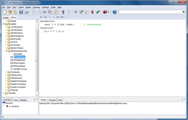
All ports of a submodel are shown in the Type window of the 20-sim Editor. In the figure below an electrical Resistor is shown with one power port p. Each port has an across and through variable. In 20-sim these variables are denoted with the extensions .a and .t. You can also use the names that are specific for a certain domain. For the electrical domain the extensions .u and .i are used. You can see an example in the figure below (Implementation section) where equations are defined using the variables p.u and p.i.
Ports can be added and defined in the 20-sim Type Editor. You can open the Interface Editor in the Interface tab (right mouse menu). The Interface Editor of the Resistor is shown below.
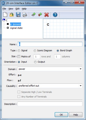
Iconic Diagram Ports have several properties:
| • | Name: The name of the port. |
| • | Type: Next to Iconic diagram ports, 20-sim also knows bond graph ports and signal ports. |
| • | Size: The standard size of a port and corresponding connection is 1 but you can also define ports with larger sizes. |
| • | Orientation: The orientation of a port defines how the though variable is connected. |
| • | Input: A positive through variable will act upon a component in the positive direction (mechanical domain) or flows into the component (non-mechanical domain). |
| • | Output: A positive through variable will act upon a component in the negative direction (mechanical domain) or flows from the component (non-mechanical domain). |
Note: The port orientation and the orientation of the corresponding connection can be made visible in 20-sim by arrows.
| • | Domain: The physical domain of the port. |
| • | Causality: The causality of the port variable (across and through). You have to define here what should be the input variable (across or through) and what should be the output variable (across or through). |
By default, an iconic diagram port is a port where power can be exchanged between a component and its environment in terms of an across variable and a through variable. Such a port is represented by one terminal. However, there are two special cases where it is desirable to define an iconic diagram port that has more than one terminal. These are the Separate High / Low Terminals port and the Any Number of Terminals port. These options are only for advanced users!
| • | Separate High / Low Terminals: Select the port to have two terminals. Only for experienced users! |
| • | Any Number of Terminals: Select the port to have any number of terminals. Only for experienced users! |