Iconic Diagrams\Hydraulics\Valves\Basic Valves
Domains: Continuous. Size: 1-D. Kind: Iconic Diagrams (Hydraulics).
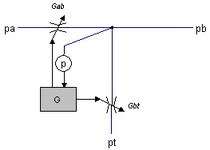
Pressure reducing valves have the purpose to provide a constant pressure (p_set), independent of the upstream pressure. They are used to limit the pressure of a primary circuit to a desired pressure for a secondary circuit.
The desired pressure (p_set) is obtained by means of a flow over a valve between an input port (pa) and an output port (pb). The valve is modeled by a variable conductance). Depending on the pressure downstream (pb.p) the valve is opened (large conductance) or closed (zero conductance). Therefore pressure reducing valves always need a small flow to establish the correct downstream pressure.

When the downstream pressure (pb.p) increases over the desired pressure a second valve opens to allow flow from the downstream port which is connected to the tank. The speed of the valve is controlled by the parameter k. If k is high (>> 10) the valve will respond quickly but can also get into oscillation more quickly. When k is small (<< 10), the valve is stable but will react more slowly.
Ports |
Description |
pa pb |
Upstream port Downstram port |
Causality |
|
fixed volume flow out pa fixed volume flow out pb |
|
Parameters |
|
p_set p_max |
Desired pressure a port b [Pa], P_set > 0. Maximum input pressure at port a [Pa], p_max > 0. |
phi_max |
Maximum flow at maximum input pressure and zero desired pressure [m3/s], phi_max > 0. |
k |
Valve gain, k > 0. |


