


|
Navigation: Library > Iconic Diagrams > Hydraulics > Pumps > displacementpump-leakage |
  
|
Iconic Diagrams\Hydraulics\Pumps
Domains: Continuous. Size: 1-D. Kind: Iconic Diagrams (Hydraulics).
Description
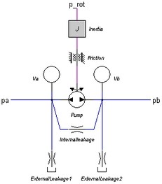
This model describes a pump with internal and external leakage and a displacement that is proportional to the speed of the input axis:
i = D * c / (2*pi);
pa.phi = pb.phi = i * p_rot.omega;
The actual flows at the inlet and outlet port may be slightly different because of the flow into the lumped volumes and the leakage flows. The leakage flows are modeled by laminar resistances. The torque of the pump is equal to:
p.T = i*(pa.p - pb.p);
If the inlet pressure is smaller than the vapour pressure(p < p_vapour), the flow is zero. If the inlet pressure becomes larger than the vapour pressure the flow gradually grows to its normal value, until the atmospheric pressure (p = 0) is reached.
Ports |
Description |
pa pb p_rot |
inlet port (hydraulic) outlet port (hydraulic) axis (rotation) |
Causality |
|
preferred pressure out pa preferred pressure out pa preferred angular velocity out p_rot |
|
Parameters |
|
D J d_m |
Displacement per revolution [m3] Rotational inertia [kg.m2] Viscous (rotational) friction [N.m.s/rad] |
p_static |
Start pressure, acts as Coulomb friction, set to 2% of max pressure if unknown [Pa] |
G_int |
Internal laminar leakage conductance, set to 1e-13 if unknown [m3/s.Pa] |
V |
Dead volume of the pump at each port [m3] |