Two types of motion profiles can be generated by the Cam wizard: intermittent steps and continuous pulses. The intermittent step motion does not return to its starting position, but gradually moves further away . It is characterized by the parameters stroke, start_angle and stop_angle.
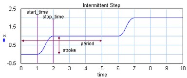
The continuous pulse motion output returns at the end of each cycle returns to the starting position. It is characterized by the parameters stroke, start_angle, stop_angle, return_angle and end_angle.

In mechanical engineering an important part of design is the reduction of vibrations. Every time a construction is in motion, vibrations are induced. When cams or mechanisms are used, the amount of vibrations, depend on the kind of motion that is induced. E.g. a sudden step change will induce violent vibrations in comparison with with a fluent motion. An important parameter to characterize motions, is the order:
| 1. | Zero Order: Motions that are discontinuous in the position (e.g. a step). |
| 2. | First Order: Motions that are continuous in the position but discontinuous in the velocity (e.g. a ramp). |
| 3. | Second Order: Motions that are continuous in the position and velocity but discontinuous in the acceleration. |
| 4. | Third Order: Motions that are continuous in the position, velocity and acceleration. |
| 5. | Fourth Order: Motions that are continuous in the position, velocity, acceleration and jerk. |
The specific shape of a motion profile can have a significant influence on the dynamic behavior. Some profiles minimize the maximum velocity, some profile minimize acceleration, while other profiles tend to make a tradeoff between the maximum velocity and acceleration. If we take a standard motion with stroke 1 and motion time 1 sec., the following table can be generated:
profile |
order |
vmax |
amax |
y(0) |
y(1/2) |
1 |
1 |
infinite |
infinite |
0 |
|
2 |
> 1.57 |
> 4.93 |
infinite |
< -15.5 |
|
2 |
2 |
4 |
infinite |
-infinite |
|
2 |
1.67 |
4.17 |
infinite |
0 |
|
2 |
2.41 |
8.49 |
infinite |
-118.5 |
|
2 |
1.57 |
4.93 |
infinite |
-15.5 |
|
3 |
2 |
4 |
32 |
-32 |
|
3 |
1.67 |
5.55 |
55.6 |
0 |
|
3 |
2 |
6.28 |
39.5 |
-39.5 |
|
3 |
1.76 |
5.53 |
69.4 |
-23.2 |
|
3 |
2 |
4.88 |
61.4 |
-61.4 |
|
3 |
1.26 |
9.20 |
173.6 |
0 |
|
MSC%4 |
3 |
1.37 |
7.20 |
113.1 |
0 |
3 |
1.88 |
5.77 |
60 |
-30 |
|
3/4 |
2.05 |
10.25 |
BB |
BM |
1: Parameter CV = 20%
2: For lw >> lc the Crank Rod profile equals the sine profile, for lw > lc performance deteriorates.
3: Parameter CV = 20%, CA = 20%
4: Parameter n = 30%, alpha = 10%
5: Parameter BB = 30%, BM = 10%
Here y(0) is the initial jerk (derivative of acceleration) and y(1/2) the crossover (halftime) jerk.
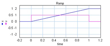
The ramp profile is a first order profile. It has a constant velocity and acceleration peaks at the start and end of the motion.
A Crank Rod mechanism converts a rotary motion into a repeating translation and
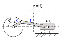
If the rod is much longer than the crank, the resulting motion profile will approach the sine profile. Below the motion profile is shown for half a rotation of the crank (angle from 0 to 180 degrees in 1 sec.).
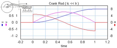
If the rod gets smaller, the maximum velocity and acceleration increase.

Note: A real crank-rod mechanism will not suddenly stop at half a rotation and therefore not show a discontinuous acceleration.
The trapezoidal profile is a second order profile. It has a constant acceleration at the start of the motion and a constant deceleration at the end of the motion.
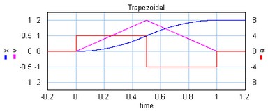
This profile is most widely used in early servo systems. Because of the discontinuity in the acceleration this motion profile can still induce a lot of vibrations. Therefore in modern servo systems third order profiles are preferred.
The partial trapezoidal profile is a second order profile. It has is equal to the trapezoidal motion, but has a constant velocity part, during a fraction CV (%) of the motion.
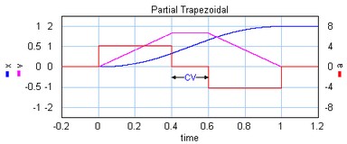
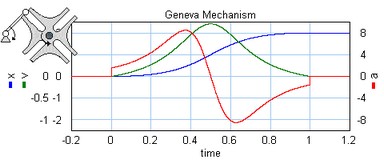
A Geneva mechanism is an old motion profile generation mechanism. A continuously rotating crankshaft (a) generates an intermittent motion of a second shaft (b). The result is a second order profile.

The motion profile generator yields the motion of the second shaft (b). It is shown below:
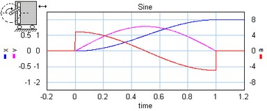
The sine profile is a second order profile of which the displacement can be described as:
x = 0.5 - cos (p * t) / 2.
The cubic profile is a third order profile of which the acceleration is constantly increasing and decreasing.

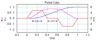
The partial cubic profile (3rd order) is a modified cubic profile with a constant velocity during a fraction CV (%) of the motion and a constant acceleration during a fraction CA (%) of the motion.
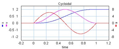
The cycloidal profile is a third order profile, of which the velocity can be described as:
v = stroke*(1-cos(t*a))
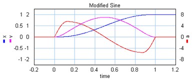
The modified sine profile is also a third order profile. It is a modification of the cycloidal profile to get a lower maximum velocity and a lower maximum acceleration.
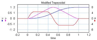
The modified trapezoidal profile is a modification of the trapezoidal profile (to make it a third order profile). This profile yields a very low maximum acceleration.
The modified sine with constant velocity profile (3rd order) is a modification of the modified sine profile. It has a constant velocity during 50% of the motion.
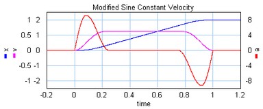
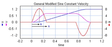
The modified sine with constant velocity profile (3rd order) is a modification of the modified sine profile. It has a constant velocity during a user definable part of the of the motion. The non-zero acceleration part is defined by two parameters which are both defined as a fraction of the motion. The first parameters alpha (%) defines the start of the acceleration and the second parameters n (%) defines the end of the acceleration.
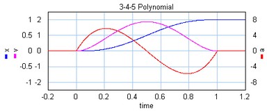
The is a third profile described by a 5th order polynomial.
The is a third/fourth order profile described by a 9th order polynomial. The profile is characterized by two parameters that denote the initial jerk, BB, and the crossover jerk, BM. If BB is chosen zero, this a a fourth order profile. If BB is chosen non-zero, this is a third order profile.
