


|
Navigation: Toolboxes > Mechatronics Toolbox > Servo Motor Editor > Theory > Basic Principles > Brush DC Motors |
  
|
In DC motors, the torque function Kc(q) is sinusoidal:
![]()
In DC motors a constant current is supplied. Through a process called commutation, the coil is connected the other way around (i.e the current changes sign) when the coil function crosses zero. The resulting torque will then always be positive but will vary between zero and maximum:
![]()
By combining coils, the resulting torque variation or ripple will decrease. The graph below shows the resulting torque when three coils are used.

The more coils are used the more the torque ripple decreases.
|
|
If we neglect the torque ripple, we get the common DC motor equations:
![]()
In practical motors, the rotor is equipped with a commutator. A commutator consists of insulated collector bars that are connected with the coils. Each coil is connected with one end to a collector and the next end to the neighboring collector. A pair of brushes is used to connect an outside current source to the collectors.
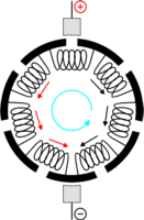
Every rotation the current changes sign twice, resulting in a continuous positive torque addition of every coil.
Commutation is the largest limiting factor in DC motor performance. Sparks between the brushes and the collectors are the main causes for brush wear. There are several causes for sparking, which limit the maximum speed, current, voltage and power of a brush DC motor.
When the brush leaves a collector, the current has to be reversed. The time that is needed to reverse the current depends directly on the current amplitude and thus on the generated torque. Because the time that is available depends on the motor speed, the result is a limit on the power that can be generated.
Another limitation of the motor speed is due to imperfect dimensions of the collectors. Differences in height of a few microns may cause the brushes to jump at high speeds.
Just a small part of the contact area of a brush and collector is actually used for the current transfer. As a result highly localized, short time "hot spots" develop. When the currents get greater than permitted, local temperatures occur that lead to material evaporation.
Above a voltage of 15 to 18V experience shows that the air will experience ionization phenomena, which leads to arcing. This arc extends from one collector bar to another. When enough voltage is applied, the arc will extend several collector bars and reach the other brush, leading to serious damage. The maximum motor voltage is therefore the result of multiplying the number of collector bars between the brushes and the maximum collector bar voltage.
Permanent magnets can lose their strength when operating above temperatures of 60 ºC and suppressed by a high external magnetic field. Such a field can occur when large current changes occur. Therefore the maximum current of a motor should be limited.