In the mechanical domain, both translational and rotational, terminals and knots can be replaced by 1 junctions. With this knowledge and the description of various icons a table can be created that shows icons of mechanical elements and their equivalent bond graph elements. The method of creating a bond graph model is:
| 1. | Create an iconic diagram of the mechanical system. |
| 2. | Reference points or grounds are split up as much as possible. |
| 3. | Replace every element of the diagram by its bond graph equivalent using the conversion table. |
| 4. | Replace every knot that has been left by a 1 junction. |
| 5. | Connect all elements and junctions with bonds, according to the layout of the mechanical system. |
Example
The method will be illustrated by an example. We will convert an mechanical structure (translational) into a bond graph model.
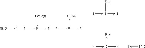
| 1. | Create an iconic diagram |

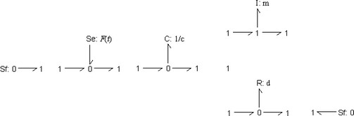
| 2. | Split up reference points. In this diagram this is not possible. |
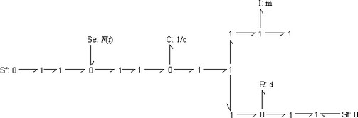
| 3. | Replace elements by bond graph equivalents. Note that we have arranged the orientation of the bonds (the direction of the harpoon) as much as possible in the direction of the power flow from the source to the load elements. |
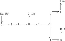
| 4. | Replace every knot that has been left by a 1 junction. |
| 5. | Connect all elements and junctions with bonds, according to the layout of the mechanical system. A comparison between the iconic diagram and the bond graph model clearly shows the symmetry between both representations. It is obvious that any change or addition in the iconic diagram, can be easily implemented in the bond graph model. |
| 6. | Simplify the resulting bond graph model. First we eliminate the Sources (Se elements) with zero output. |
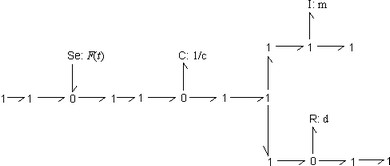
| 7. | Eliminate loose junctions. |
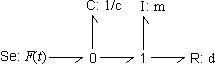
The simplified model does not show a direct symmetry with the iconic diagram. It does give a clear insight in the flows of power from the force source to the other elements.


