


accumulator |
  
|
Iconic Diagrams\Hydraulic\Volumes
Domains: Continuous. Size: 1-D. Kind: Iconic Diagrams (Hydraulics).
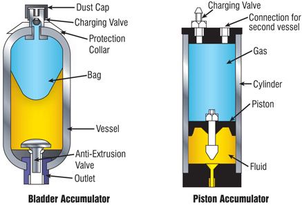
Accumulators consist of a gas filled chamber, pressurized by an oil filled chamber. The chambers are separated by a bladder or piston. If oil enters the chamber the gas chamber will reduce in size and the pressure will rise. If the oil pressures sinks, the gas chamber will expand and drive oil out of the oil chamber. The accumulator thus acts a a storage of hydraulic energy. Most accumulators are filled with nitrogen gas which is also used in this model. You can change to other gasses by changing the gas parameters.
When preparing an accumulator for use with the oil at ambient pressure, the gas is pre-charged to a certain pressure p_pr. The gas chamber will expand its maximum size which is called the accumulator volume V. During operation, oil will flow into the chamber and the gas chamber will change size. The oil and gas pressure will be in balance and indicated with the gas pressure p_gas. The resulting gas volume is name V_gas. We assume that during pre-charging the gas temperature is constant and equal to the ambient temperature T_amb. During operation, the gas temperature may change but the ambient temperature is assumed constant.
Due to compression, the gas temperature will increase and the accumulator will heat up. This heat may be lost to the environment. In this model the heat loss is modeled by a first order transfer function using a thermal time constant tau. If the accumulator is heated up and the gas keeps its volume, an exponential temperature decrease will be found. The thermal time constant is the time where the temperature is decreased by 63%. However, the gas will be compressed if the temperature sinks. As a rule of thumb take for the thermal time constant the time it takes for the temperature to sink by 50%. By making tau infinite, the accumulator does not convert heat to the environment.The change is gas volume is then called adiabatic expansion or compression. By making tau very small, the accumulator instantly convert all heat to the environment.The change is gas volume is then called isothermal expansion or compression.
The accumulator model is based on the Van der Waals equation for a real gas. This model takes into account that gas gas particles have finite size and attractive forces. The Van der Waals model uses the critical gas temperature T_cr and the critical gas pressure p_cr as parameters. By taking the parameter T_cr = 0 the Van der Waals model changes into the ideal gas model.
By changing the parameters, the accumulator model can represent various gas models:
1) Ideal Gas: set T_cr = 0
2) Ideal Gas, Adiabatic Expansion: set T_cr = 0 and tau very large (i.e 1.0e9)
3) Ideal Gas, Isothermal Expansion: set T_cr = 0 and tau very small (i.e 1.0e-9)
4) Real Gas: set the critical temperature of the gas (i.e. nitrogen: T_cr = 126.2 {K}) and set the thermal time constant to a specific value
Ports |
Description |
p |
hydraulic port |
Causality |
|
fixed volume flow out |
|
Parameters |
|
G V p_pr p_oil T_amb tau R_s c_v T_cr p_cr |
conductance of the accumulator input [m3/s.Pa]. max gas volume of the accumulator [m3] pre-charge pressure [Pa] oil pressure at the start [Pa] ambient temperature [K] thermal time constant [s] specific gas constant [J/kg.K] specific heat of the gas at constant volume [J/kg.K] critical gas temperature [K] critical gas pressure [Pa] |