


|
Navigation: Modeling Tutorial > Iconic Diagrams > Orientation (Across) |
  
|
When simulating, you have to know how across and through variables are oriented to make a correct interpretation of what is happening. 20-sim can show the orientation when you select the Orientation Info option of the View menu.
Across variables in the top level of a model are always defined with respect to a single global reference. In the picture below an electrical iconic diagram is shown with three voltages (u1 = 5 V, u2 = 3 V and u3 = 1 V). This means these voltages are all defined with respect to the same reference, e.g., the ground u = 0 V.
All variables values of a connection can be easily inspected during simulation by placing the mouse pointer on top of that connection as shown below. The connection between the mass and the spring (see picture below) shows an across value v = 0.84 m/s. This means the point where the mass and spring are connected has a global velocity of v =0.84 m/s.
In the figure below the connection between the capacitor and the resistor shows a negative voltage of u = -2e-5 V.
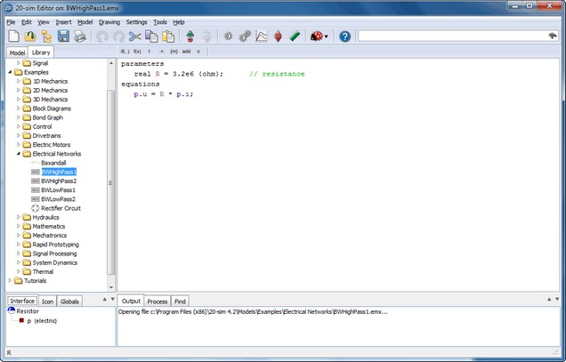
In submodels you have to inspect how across variables are defined. For example an ideal electrical resistor (see figure below) uses separate high and low terminals. The internal equations are:
p.u = p_high.u - p_low.u;
p_high.i = p_low.i = p.i;
p.u = R * p.i;
where p.high and p_low are the ports to the connections at both sides of the resistor. p_high.u and p_low.u are voltages defined with respect to the global reference, but p.u is the voltage difference between the high and low port and therefore not defined with respect to the global reference.
The definition of across variables depends on the definition of number of terminals of a port, which is shown in the Type Editor. To inspect the ports, put the mouse pointer on top of the Type section and select edit type from the right mouse menu.
| • | The geometrical layout of the iconic diagram does not have a meaning. If a resistor is drawn upside down, its current is still defined with respect to the resistor (flowing towards or from). If a mass is drawn upside down, its force is still defined with respect to that mass (pulling or pushing). |
| • | To show or hide the orientation of an Iconic Diagram select or deselect the Orientation Info option of the View menu. |