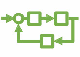
Block Diagrams
Block diagrams allow you to graphically represent the mathematical relationships between signals in a system. They are especially suited to model control systems. In 20-sim a large library of block diagram elements is available. The elements are displayed in the Editor by icons. You can create block diagram models by dragging the elements to the Editor and making the proper connections between the elements. 20-sim allows you to create user defined block diagram elements with an arbitrary number of input and output signals. Signal sizes can be 1 (default) or larger.
Library
20-sim has a large library of block diagram elements such as linear, non-linear, discrete and source elements. In 20-sim you can create custom made block diagram elements and add them to the existing libraries or combine them in newly defined libraries. From the Library Browser (left) you can drag and drop elements into the Editor (right).
Read More
You can find more information on the Block Diagram library and the blocks that are contained in this library in the 20-sim webhelp.