
Iconic Diagrams
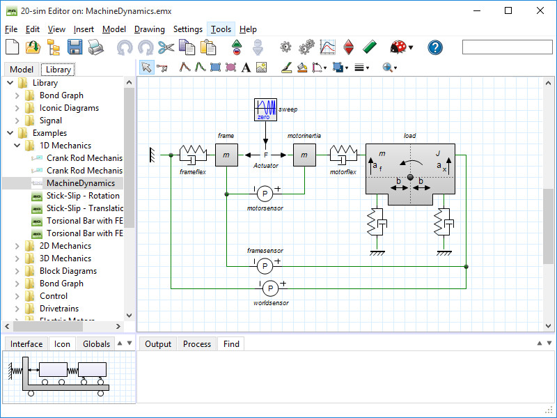
Iconic diagrams or components are the building blocks of physical systems. They allow you to enter models of physical systems graphically, similar to drawing an engineering scheme. In 20-sim a large library of iconic diagram elements is available. The elements are displayed in the Editor by icons which look like the corresponding parts of the ideal physical model. You can create models by dragging the elements to the Editor and making the proper connections between the elements.
Library
20-sim has a large library of iconic diagram elements such as electrical, hydraulic, mechanic and thermal models. In 20-sim you can create custom made iconic diagram elements and add them to the existing libraries or combine them in newly defined libraries.
Ports and Multiports
The foundation of iconic diagram elements is the use of power ports. Power ports form the connections with iconic diagram elements and consist of two mutual signals which are called across and through. 20-sim allows you to create user defined iconic diagram elements with an arbitrary number of power ports and signals. Ports sizes can be 1 (default) or larger (multiports).
Algebraic Loops and Differential Causality
Algebraic loops and differential causalities are traced automatically. If possible, 20-sim will rewrite the equations symbolically to remove algebraic loops and differential causalities.
Custom Made Models
In 20-sim you can create your own iconic diagram elements and save them in your own model library. Models can have an arbitrary number of ports, input and output signals. A specialized drawing editor can be used to give the models any kind of representation.
Read More
You can find more detailed information on the iconic Diagram library and the blocks that are contained in the 20-sim webhelp.